


As anyone with a succession of successfully executed Coiled Tubing Drilling jobs under their belt might tell you, ‘Coiled Tubing Drilling is Great! It’s a lightweight, small footprint, highly flexible environmentally friendly operation, with a low staff count and a small fuel burn. Tripping speeds are fantastic, pressure control is excellent and thanks to the inherent ability to drill underbalanced, reservoir damage is unheard of.’
And yet, depending on the company you keep, you may be equally likely to run in to someone who will tell you, “It’s a fiddly, trouble-prone operation. You can’t get weight to the bit, you can’t clean the hole, the tools get stuck and fatigue breaks the CT.
It is a fact that there are some drilling jobs totally unsuited to CTD, and those who hold the latter view are likely to be those who have been burned trying to use CTD in situations where it has no hope of delivering on its claimed advantages.
The way to avoid being burned is to thoroughly appraise the proposed job beforehand, including full computational modelling of the operation. It is the computational modelling that is the subject of this series of blog articles that will be posted over the coming weeks.
The success of a CTD project depends on three fundamentals:
1) Tubing Forces To be successful it is necessary to be able to convey the bit to the bottom of the hole with enough push left over to engage the bit with the formation and maintain positive Weight On Bit.
2) Hydraulics Success depends on the ability to circulate enough fluid through the coil and the BHA to power the mud motor and clean the hole while maintaining the bottom hole circulating pressure in a tightly defined window – high enough to prevent the hole collapsing yet low enough to avoid formation skin damage through fluid invasion.
3) Fatigue Management Every time a length of CT comes off the reel, over the guide arch and in to the hole it experiences 3 episodes of plastic deformation. Repeated plastic deformation can rapidly add up to catastrophic failure. The number of cycles to failure turns out to be strongly dependent on the pressure inside the CT when the plastic deformation takes place. Success depends on managing this fatigue by tracking every motion of a reel of CT throughout its life, in conjunction with the pressure present so that the coil can be removed from service before it has accumulated enough fatigue cycles to fail catastrophically. Virtual jobs can be modelled in advance, and the results combined with the history of a candidate coil to determine whether a particular coil can be used for a project without exceeding its fatigue life.
All three of these fundamentals can be modelled, using fit for purpose software such as AnTech’s ATLAS™ software. The results of modelling give an unambiguous indication of whether or not a proposed project is a good candidate for CTD.
For the remainder of this article we will concentrate on tubing forces modelling. The other fundamentals will be covered in future articles.
Tubing forces modelling
Imagine a vertical hole in which a Drilling BHA is deployed on Coiled Tubing. When the bit reaches the bottom of the hole (fig 1a), a first order approximation of the available weight on bit can be made by adding the weight of the BHA to the product of the CT’s weight per foot and the depth of the hole.
The CT is a tall slender column, and the approximation above holds true until the column buckles. Once the column buckles, there is a frictional interaction between the outer walls of the CT and the inner walls of the hole (fig 1b).
The load level at which buckling commences is a well understood function of the CT’s dimensions and material stiffness, and the frictional forces due to the interaction between the buckled CT and the wall are primarily a function of the difference in size between the CT and the hole it is in.
Now consider that we have drilled a build to horizontal at the bottom of our vertical hole, followed by several hundred feet of lateral.
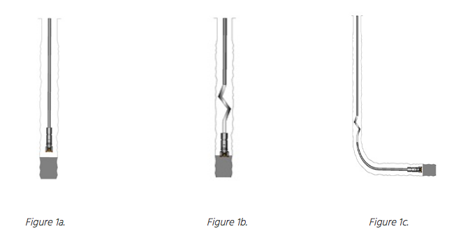
When the BHA is in the lateral (Fig 1c), it is still the weight of the CT in the vertical section that is the motive force propelling the BHA sideways (except in very shallow cases where the injector’s snubbing ability may be usefully used to assist); and as in the vertical case, this force is potentially moderated by buckling. Additionally, frictional forces due to the weight of the BHA and the CT on the bottom of the lateral act to oppose the driving force. As the lateral gets longer a point will be reached when these frictional forces outweigh the propelling force and the hole will cease to progress.
If you are an engineer putting a project together, what you want to know is whether or not you will be able to generate sufficient WOB to drill at all points along the proposed wellbore’s trajectory.
ATLAS™ is designed to deliver just that. All it requires is a trajectory and the details of any existing completion that the tool string will be running through, details of the BHA and CT, and the density and viscosity of the drilling fluid being used. ATLAS’s headline tubing forces output is a chart showing achievable WOB against measured Bit Depth. Also shown is Injector load, and a minimum WOB threshold for drilling.
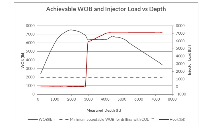
Figure 2. Atlas primary tubing forces output. Achievable WOB vs Depth
This output enables the engineer to determine at a glance whether his chosen CT and BHA configuration will reach the end of the hole with enough available weight on bit to drill.
In the case shown in figure 2, there is still 3000lb available WOB predicted at the end of the hole, so the engineer knows he is good to go. His next step will be to consider the hydraulic aspects of the job. These will be discussed in the next blog.
Author: Richard Stevens


%E2%80%8B.jpg)


